


Split AC Wiring
AC Wiring
As Summer is coming soon many people think to install new Air conditioner for their homes. Basically for homes there are two types of air conditioner available in market as given below:
- Window AC
- Split AC
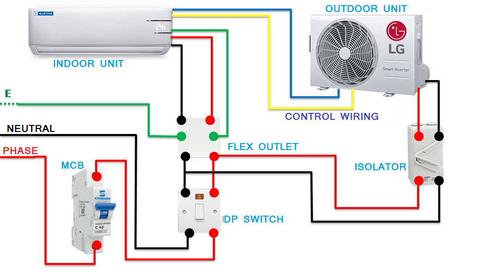
Window AC is installed in window’s only as the name itself perdicts Window AC. Split AC can be installed in any room at any location but Split AC consists of two units Indoor Unit and Outdoor Unit, so its wiring is difficult as compared to window AC. Here we would discuss the wiring of window ac and complete accessories required to install with window AC for its proper functioning.
Material list required to install window AC
- Miniature Circuit Breaker
- Double Pole Switch
- Flex Outlet
Minature Circuit Breaker (MCB)
MCB is a device that provide short circuit and overcurrent protection to the equipment. If there is any kind of short circuit takes place in wires or in ac circuit then MCB trips due to large current flowing and saves the AC from damage.
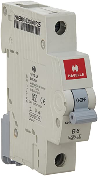
Also when AC takes large current due to overloading of motor and compressor then in that case also MCB trips and saves the equipment from any damage. So MCB is most important device to be used in window AC circuit.
Also Read
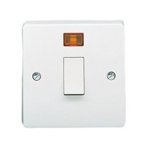
DP Switch
DP Switch is also called Double Pole switch It is also used with window AC Its mainly a switch consists of both live wire and neutral wire, This switch is operated manually and can control both phase and neutral simultaneously.
Also watch Video on Wiring of Window AC
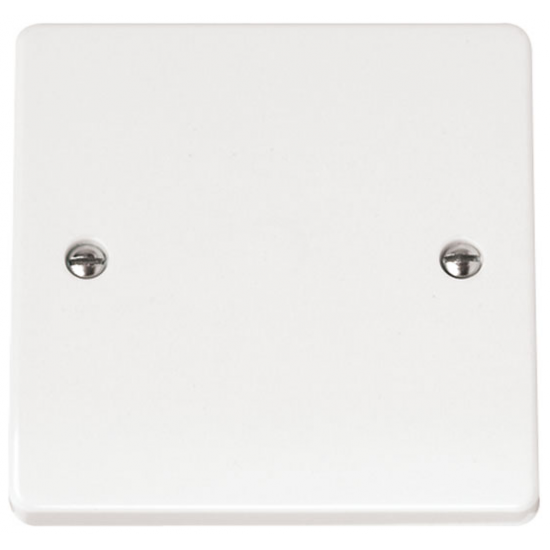
Flex Outlet
Flex Outlet is basically a connector that connects phase, neutral and earth wire and also consists of fuse system in phase that prevents window AC from any kind of sparking,voltage fluctuations etc.
All devices has discussed and required for wiring connection of Window AC Now complete wiring of all devices along with Window AC has shown below:

I hope you will get complete knowledge of Window AC wiring and this article helps you, Thanks for reading this article
My Youtube Channel
Positive and negative terminals in a polarized capacitor?
All electrolytic capacitors are polarized, and carry markings to identify polarity of terminations.
Most small aluminium electrolytic capacitors carry a stripe on negative terminal side. In case of axial lead aluminium electrolytic capacitor, the stripe also carries arrow marks to point to negative terminal.
In addition, when lead wire are used as output terminals, negative terminal lead is shorter. So it çan be identified independent of other markings.
Large aluminium electrolytic capacitor with terminal disc has often red mark at base of + terminal.
In case of tantalum axial capacitor, often a + mark is placed to identify positive terminal.
What is polarization in a capacitor?
Not all capacitors are polarized, ones that are will be clearly marked with + and – where the leads go into the case.
Polarized capacitors are a type of capacitor called an electrolytic capacitor in which a chemical reaction on the surface of the capacitor’s anode forms an oxide layer that serves as the capacitor’s dielectric separator. Reversing the polarity would cause the oxide layer to dissolve causing the capacitor to short circuit, hence the need to be polarized.
Electrolytic capacitors are typically cylindrical with both leads coming out of one end of the can. They can be quite large. Failed electrolytic capacitors can split or even explode.
What does polarized capacitors mean?
A polarized capacitor has a dielectric material in it similar to the acid in a battery.
Capacitors consist of a sandwich of two conductors separated by an insulator. In a polarized capacitor the insulating material is a dielectric, meaning it becomes a dipole when the capacitor is charged.
Ordinary capacitors do not have a positive and negative side, but polarized capacitors do have a positive side and a negative side. When they are connected to a circuit you must take care to connect the positive side to positive and the negative side to negative. Failure to connect it properly could damage the capacitor. Under some circumstances it could overheat and be dangerous.
The large capacitance of electrolytic capacitors makes them particularly suitable for passing or bypassing low-frequency signals, and for storing large amounts of energy. They are widely used for decoupling or noise filtering in power supplies and DC link circuits for variable-frequency drives, for coupling signals between amplifier stages, and storing energy as in
Cable Selection
Since There are different sizes and types of cables available in market, we have to do cable selection to be used at specific location according to the usage. Types of cables are as follows:-
- Copper Cable
- Alluminium Cable
Also Copper and Aluminium cables are available in different sizes like 1 sq.mm to 300 sq.mm and different sizes carry different currents and also different gland sizes. One can do cable selection to be used after checking the current taken by cable which can be selected easily from below tables
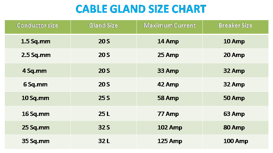
From above table one can easily learn about copper cable size from 1.5sq.mm to 35 sq.mm their gland size, current carrying capacity and breaker to be used for particular cable.
Also we are providing a table of copper cable size 50sq.mm to 300sq.mm having complete specifications of gland size, current carrying capacity and breaker size. Kindly have a look
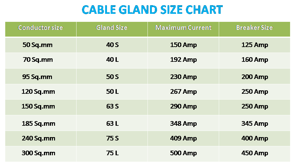
So In this article you have learned about copper cables and easily perform cable selection for particular job from these tables.
Youtube Channel :- Electrical Stuff 4u
Does fire conduct electricity?
Fire basically conducts electricity the same way salty water does: both contain some concentration of charged particles that are free to move.
Water contains some concentrations of ions and protons (H++ protons). When there is a voltage difference, the ions will move according to their charge.
The hot gas of the flame contains positively charged ions and electrons, which will move in the same way as the ions in the water. The reason there are ions is that the heat of the gas is such that some of the electrons can free themselves from the attraction of their atoms.
For sure! Fire is a plasma, and plasmas have freely-moving charged particles within them. Anything that has freely-moving charged particles conducts electricity.
So metals, which have a sea of mobile negatively-charged electrons on their surface, conduct electricity. And saltwater…
Godown Wiring
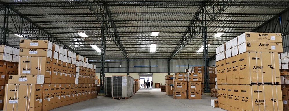
Today In this world we are using large quantity of products in our day to day life, So there is huge demand of different products in bulk but one can’t manufacture products simultaneously. Now to satisfy the demand we have to keep the products ready in large godown or store rooms. Every one has watched once in a life below shown godown in their life.

These pictures shows ware house which we use to store large quantity of different types of products, Now here is the question How can one provide light arrangement for such large ware houses because these godowns are so large that if we can use simple lighting techniques which we use in complexes then large consumption of electricity would takes place which results in electricity wastage.
Since while working in godown if we switch on whole lighting system then all lights will glow which is wastage of energy as we only need the light in particular section where we have to work and not in whole warehouse, so this lighting technique is not energy efficient.
Solution
To tackle this situation we have to use godown wiring technique, by using this technique one can only lighten the particular section of godown where we have to work and the remaining section remains in dark which results to energy saving.
Series and Parallel Connections of Resistance
Godown Wiring
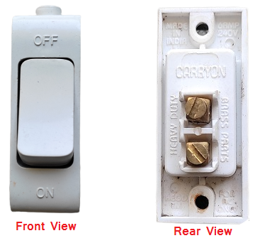
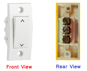
Godown wiring is a technique which we used in large ware houses for lighting purpose, In this technique we use two way switches as well as one way switch Now the question is what is one way switch and one is two way switch ?
So the answer to this question is one way switch has only two terminals while two way switch has three terminals one can easily differentiate between the by only watching their terminals you can also give a look to below pictures of one way and two way switches.
After watching these pictures you will learn about one way ans two way switches now the question rises how to use this now before these switches in godown wiring we have to learn about the combination of switches used so here is a simple thumb rule that if we have to use 10 number of bulbs in our godown then we have to use total 10 switches for 10 bulbs. out of 10 switches we have to use 9 two way switches and 1 one way switches. Similarly let’s take another example if we have to use 20 bulbs in godown then we have to use 19 two way switches and 1 one way switch, this is the way to use the combination.
Now another question is circuit diagram to be used to connect all these switches and bulbs in godown wiring so here is the answer below

The above circuit shows the godown wiring of total four bulbs which we are doing with the help of 3 two way switches and 1 one way switch as discussed in above paragraphs, Now one have to follow same circuit for any number of bulbs to be connected and easily do the godown lighting connections.
You can also watch video on godown wiring on the link below:-
Godown Wiring Video
I hope you like this article and learn a lot from this, for such kind of electrical related articles kindly follow my website and also my youtube channel Thanks.
Youtube Channel :- Electrical Stuff 4u
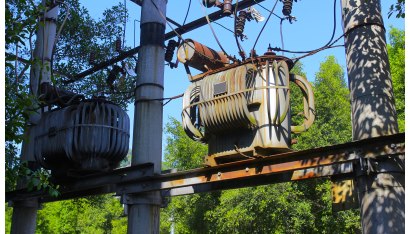
What is the meaning of DYN11 in a transformer?
Dyn11 is vector group notation of tansformer.It means LV winding,which is star connected (written in small letters means LV side and vice versa)is 30 degrees lagging by HV winding which is delta connected.In India we go for +-30 deg connection of transformer.
D = Delta connection at primary,y = Star connection at secondary and n = neutral point connected at secondary.
Dyn 11 means that the voltage of the secondary star winding lead the primary phase voltage by 30 degree and it corresponds to 11 o’clock.
Also Watch My Youtube Channel
The primary is connected in Delta form the secondary in Y or star form the neutral is grounded and the 11 means that the phase angle between the primary and the secondary winding is 30×11=330=-30 degrees. which means that the secondary voltage leads the primary voltage to 30 degrees.
Also Read

Power System MCQ
1.The charging current in a transmission line
- Lags the voltage by 900
- Leads the voltage by 450
- Leads the voltage by 900
- Leads the voltage by 1800
Answer: 3
2. As the transmission voltage increases, the percentage resistance drop
- Increase
- Decrease
- Remain same
- None
Answer: 2
3. The coefficient of reflection for current for current for an open ended line is
- 1
- 0.5
- -1
- 0
Answer: 3
4. Ferranti effect on long overhead line is experienced when it is
- Lightly loaded
- On full load at upf
- On full load at 0.8pf
- On full load at zfp
Answer: 1
5. For an overhead line, the surge impedance in taken as
- 40 ohm
- 80 ohm
- 100 ohm
- 400 ohm
Answer: 4
Also Read
Series & parallel connections of Resistance
6. For a good voltage profile under no load conditions a long line needs,
- Shunt capacitors at receiving end
- Shunt reactors at receiving end
- Shunt resistance at receiving end
- Shunt capacitor at sending end
Answer: 2
7. Corona loss is on hilly areas than as plains areas
- less
- Same
- more
- None
Answer: 3
8. In any transmission line, AD-BC=
- 1
- 0
- -1
- 2
Answer: 1
9. If the p.f of load decrease, the line losses,
- Increase
- Decrease
- Remain same
- None
Answer: 1
10. The nature of line constants in the rigorous solution of transmission line is
- Distributed parameter
- Lumped parameter
- Both
- None
Answer: 1
My Youtube Channel
Transformer MCQ
1. No –load test on a transformer is carried out to determine
- Copper loss
- Magnetizing current
- Magnetizing current and no-load loss
- Efficiency of the transformer
Answer: 3
2. The main purpose of performing open –circuit test on a transformer is to measure its
- Cu loss
- Core loss
- Total loss
- Insulation resistance
Answer: 2
3. During short –circuit test, the iron lose of a transformer is negligible becauseer is to measure its
- The entire input is just sufficient to meet Cu losses only
- Flux produced is a small fraction of the normal flux
- Iron core becomes fully saturated
- Supply frequency is held constanton resistance
Answer: 2
4. In operating a 400 Hz transformer at 50 Hz
- Only voltage is reduced in the same proportion as the frequency
- Only KVA rating is reduced in the same proportion as the frequency
- Both voltage and KVA rating are reduced in the same proportion as the frequency
- None of the above
Answer: 2
5.Transformer are rated in KVA instead of KW because
- Load power factor is often not known
- KVA is fixed whereas KW depends on load p.f.
- Total transformer loss depends on volt-ampere
- It has become customary
Answer: 3
Also Read:
Resistance in series and parallel connection
6. What is Transformer?
- Transformer is a device used to convert low alternating voltage to a high alternating voltage
- Transformer is a device used to convert alternating current to direct current
- Transformer is a device used to convert low alternating current to a high alternating current
- Transformers are used only for low alternating voltage
Answer: 1
7. Transformer ratings are given in _____________
- kVA
- HP
- kVAR
- kW
Answer: 1
8. What is the current transformer?
- transformer used with an A.C. voltmeter
- transformer used with an A.C. ammeter
- transformer used with an D.C. voltmeter
- transformer used with an D.C. ammeter
Answer: 2
9. Current transformers are _______________
- parallel connected type of instrument transformers
- series connected type of instrument transformers
- parallel connected normal transformers
- series-parallel connected type of instrument transformers
Answer: 2
10. Which of the following is not a part of transformer installation?
- Breather
- Conservator
- Exciter
- Buchholz relay
Answer: 3
My Youtube Channel