Ravi

Why does Geyser switch melted ? Common reasons explained.

Hey guys Now a days use of Electrical geyser is increasing day by day at our homes. During winter season we can’t imagine to take our bath with cold water so for heating of water either we do it by gas burner (chullah) which is very costly and inconvenient for everyone, Another easiest way to heat water is with Electric Geyser.

When we install new geyser at our homes we found that there is regular melting of geyser switch,socket and wires used for geyser. As a result question rises why it is happened As we are also using various other electrical appliances at home but there is no melting of switches takes place. There are various reasons behind the melting of switches like loose wiring, improper Ampere of switch and sockets used for geyser. Following are the reasons given below:-


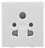
Improper Ampere switch or socket

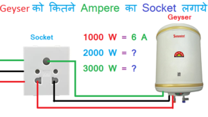
Every switch or socket used at home have some current (ampere) carrying capacity, Lets take an example if a switch /socket is capable to handle 5 Amp of current, but if we connect an appliance to that socket that consumes more current say 10 Amp then due to overloading socket gets overheated and melt or burn. Ampere is the measuring unit for calculating electricity handling capacity of switch or socket. so we have to choose proper size ampere handling switch which is directly related to Geyser Wattage. Since Wattage differs from one geyser to another then question arises how can we find the proper size of socket which is suitable for geyser, we have to use the following formula to find the ampere rating of socket required.

Ampere  =    Geyser’s Watts / Electricity Voltage

For example, Geyser wattage is 2000 Watts and Electricity supply Voltage is 220v

Ampere = 2000/220 =  9 A         

Since in general switches or socket the actual ampere capacity is 80% of the given amperes, this is known as Safe Max Ampere. Now for 9 A, the nearby Safe Max Ampere is 12.8 A with respect to the 16 A switch which means we have to go with 16 A switch/socket for 2000 Watt geyser. If we use less than 16A switch socket for 2000 watt geyser then that will melt/burn in future.

Also read:

Godown Wiring

Why do we need Transformer ?

Now lets take another example Geyser wattage is 3000 Watts and Electricity supply Voltage is 220v

Ampere = 3000/220 = 13.6 A        

for 13.6 A, nearby Safe Max Ampere is 16 A with respect to the 20 A switch which means we have to go with 20 A switch/socket for 3000 Watt geyser. If we use less than 20A switch socket for 3000 watt geyser then that will melt/burn in future.

So above calculation helps to choose the correct size of switch/socket required for Geysers wattage. In most cases people replace old geyser of 2000 watt with new geyser of 3000 watt without bothering about the electric switch/socket. since old geyser i.e 2000 watt was running on 16 A socket whereas new geyser i.e. 3000 watts require 20 A socket, but due to lack of knowledge people don’t replace switch and socket as a result after few days socket/socket get burn/melt.

So Here we conclude that if Geyser switch/socket burns/melt, first check switch/socket ampere is suited to the Geyser wattage or not. if not, replace immediately with correct ampere rating switch/socket.

Geyser switch
Geyser switch
Geyser socket
Geyser socket


After long time Switches/socket become old, worn out corroded or damaged, so it looses current handling capacity results in excessive heat buildup, resulting in melting and burning. Also Low quality switches are made of iron like metals which can be easily corroded with moisture ,leading to a short circuit and overheating. So always for brass made switches/socket of branded company.

Incorrect wiring/loose connection

Improper wiring from MCB main board to Geyser like sharing of geyser wiring with other appliances like lights, fans etc. Always go with separate circuit for geyser wiring from MCB main board, never share geyser wiring circuit with any other appliances. Also use proper size of wire required for geyser wattage, if use lower wire size then it gets overheated causes arcing, sparkling in switches/sockets.

Also Visit my Youtube Channel for electrical videos

Electrical Stuff 4u


What are the method to determine the current carrying capacity of the cable ?

Cables are used for transfer of electrical energy, cable can carry current depending on various factors below:

  1. By considering cross sectional area of cable, since cross sectional area of conductor is directly proportional to the amount of current carried by the cable.
  2. Resistance of conductor is inversely proportional to the current carrying capacity of cable so we have to consider resistance of cable.
  3. Heat generated in a conductor is directly proportional to the square of the current flowing through it. The maximum amount of current that can flow through a cable without causing a rise in temperature above the permissible limit is considered its current carrying capacity.

Also read

Does fire conduct electricity?

One have to keep this in mind that current carrying capacity of cable affected by factors like temperature, voltage drop and installation method, so before selecting cable for appropriate application one have to consider all above factors or it is advisable to consult qualified Electrical Engineer who have expertise in cable selection.

Also Visit my Youtube Channel for electrical videos

Electrical Stuff 4u

Vector group of Transformer

Introduction

In today’s world we are using single phase transformers as well as three phase transformers, In three phase transformer there are three sets of primary winding as well as three sets of secondary windings one set for each phase. Also we can use three number separate single phase transformers and then interconnect the three single phase transformers externally to work as 3-phase transformer. Before interconnecting two transformers externally one should well aware about vector group of transformer otherwise there are chances of short circuit when transformers gets energized.

There are several ways of connecting primary windings, Most common configurations are follows:

  1. Delta Connections :- When the Polarity end of one winding is connected to the non-polarity end of the next winding then that connections are delta connections.

2. Star Connections :- When all the three polarity ends connected or all three non polarity ends connected together then that configuration is called star connections.

Now we can connect primary winding and secondary winding either in a similar fashion or in different manner i.e. delta-delta, or star-star or delta-star or star-delta.

Also Read :-

When primary and secondary winding connected in a similar fashion i.e. delta-delta or star-star then it is required that secondary voltage waveforms are in phase with the secondary waveforms and this condition is called ” no phase shift “.

But when primary and secondary winding connected in a different manner i.e. delta-star or star-delta, secondary waveforms will differ from corresponding primary voltage waveforms by 30 electrical degrees. This is called 30 degree phase shift.

Winding connection designations

First symbol of vector group indicates High Voltage and always used in capital letters shown :- D= Delta, Y=Star, Z=Interconnected star, N=Neutral

Second symbol of vector group indicates Low Voltage and always used in small letters shown:- d=delta, y=star, z=interconnected star, n=Neutral

Third symbol indicates Phase displacement expressed as the clock hour number (1,6,11)

Let’s take an Example – Dyn11

Here Dyn11 indicates:-

  • First letter (D) indicates that primary winding i.e high voltage of transformer is delta connected.
  • Second letter (y) indicates that secondary of transformer is star connected and (n) indicates the star point brought out neutral
  • Third letter (11) indicates that there is a phase shift of 30 degree leading, As 11 shows position of clock when time on clock is 11’o clock.

Why Power Plant capacity rated in MW and not in MVA

Ravi answered

A Power Plant capacity is rated in MW and not in MVA due to following reasons:-

In a power generating station Prime mover i.e. Turbine generates only active power in Watts, Prime mover then rotate generator coupled to this which then converts mechanical power into electrical energy which is further transmitted to transmission lines and then electrical energy being used at homes shops etc. So that we express power plant capacity rating in MW and not in MVA. Which means no matter how large your generator is, but it depends on capacity of Prime mover or turbine i.e. a 50 MW turbine connected to a 90 MVA generator in a power plant will generate only 50 MW power at full load.

Or you can say a power plant rating is expressed in terms of Prime mover/ turbine and not by alternator set coupled to the turbine.


  • Why does Geyser switch melted ? Common reasons explained.

    Hey guys Now a days use of Electrical geyser is increasing day by day at our homes. During winter season we can’t imagine to take our bath with cold water so for heating of water either we do it by gas burner (chullah) which is very costly and inconvenient for everyone, Another easiest way to…


  • What are the method to determine the current carrying capacity of the cable ?

    Cables are used for transfer of electrical energy, cable can carry current depending on various factors below: By considering cross sectional area of cable, since cross sectional area of conductor is directly proportional to the amount of current carried by the cable. Resistance of conductor is inversely proportional to the current carrying capacity of cable…


  • Vector group of Transformer

    Introduction In today’s world we are using single phase transformers as well as three phase transformers, In three phase transformer there are three sets of primary winding as well as three sets of secondary windings one set for each phase. Also we can use three number separate single phase transformers and then interconnect the three…


Robert answered

MVA is the apparent Power i.e. simple product of voltage and current and the power which is supplied and transmitted from generator to load.

MW are the “Real Power” that perform advantageous work, it is always lower than apparent power by an amount called Power factor, power factor less than 1 are caused by load impedences that are not pure resistance.


What LED bulb is equivalent to 100 watt Incandescent bulb?

Ravi answered

Efficiency of bulbs are usually measured in lumen per watt.

So for incandescent bulb efficiency is 15 lumens per watt, it means a 100 watt incandescent bulb efficiency is 1500 lumens.

LED bulb efficiency is 100 lumens per watt now to get 1500 lumens we need 15 watt led bulb. Therefore 15 watt LED is equivalent to 100 watt incandescent bulb.


Pari answered

Incandescent bulb gives 12 lumens/watt.

Fluorescent tubes (commonly known as bar lights) gives 40 lumen/ watt, LED (light emitting diode) gives 129 lumens/ watt theoretically now since we have to achieve 100 lumens/watt, so approximately 12 Volt led can give lumen output equivalent to 100 watt bulb.

Why is Transformer rated in KVA and not in KW ?

Transformer is a device that transfer electrical power from one circuit to another circuit without changing input power and frequency. Or one can say it can step up and step down the voltage while power and frequency remain constant.

Also there are two types of losses in transformer :-

  1. Copper losses

2. Iron losses or Core losses

In transformer Copper loss depend on current flowing through the winding of transformer, while Iron loss depend on Voltage which means total loss of transformer depends on voltage and current which is expressed in VoltAmpere VA and not on load Power factor (P.F.). So Transformer rating is expressed in VA or KVA and not in W or KW.

How to buy Right Air Conditioner in 2023?

The summer of 2023 is here and getting hot day by day, Air cooler is good to lower down the room temperature but it can’t remove moisture content from air as it can’t dehumidify the air as a result the room environment is clammy so Air conditioner is best suited for summer.Now the question arises which is right air conditioner to be installed a per your room specifications.

As different sizes of Air conditioner available in market like 0.8 Ton, 1 Ton, 1.5 Ton, 2 Ton, 2.5 Ton, 3 Ton, 3.5 Ton. so we have to choose one particular Ton of AC as per specifications of rooms.

How to calculate AC tonnage for room

The actual method of finding AC tonnage for room is very confusing as it consists of British thermal unit (BTU) 1 Ton equals 12000 BTU. but here we tell you the simple method to find out the AC tonnage for room, firstly we have to find out the volume of room now the question arises how to find out the volume of room which is very simple.

Volume = (Length * Breadth * Height) in cubic feet

As shown above this is design showing the room, here l indicates the length of room now you have to simple measure the same length of your room with the help of measuring tape in feets. b donates the breadth and h donates the height of room. so you have to measure all the three dimensions of room and calculate volume in cubic feet.

Once you calculate the volume of room Divide the volume of room by 1000 and you will get AC tonnage required for room size.

Also Read :

This is not the exact AC tonnage required for room as there are also various other factors affecting the ac capacity required for your room listed below:-

  • Whether Direct sunlight falling on your ceiling (because if you are living on top floor then direct sunlight strikes on your ceiling on the other hand if you are living in ground floor and its a double story house i.e. there are floor above that room then sunlight don’t strikes directly over the ceiling.
  • The place you live is very hot or moderate type climate.
  • The Positioning of windows of room.
  • Number of people residing in the room

The table below shows the right AC tonnage required for your room. While preparing this table we have assumed-

  • 3-4 people residing in the room
  • Average height of room from floor to ceiling is 10 feet.
Area of RoomCooling RequirementRecommended AC Tonnage
100 Sq ft0.9 tons1 ton ac
120 Sq ft1.0 tons1 ton ac
150 Sq ft1.3 tons1.5 ton ac
160 Sq ft1.4 tons1.5 ton ac
170 Sq ft1.5 tons1.5 ton ac
200 Sq ft1.7 tons2 ton ac
250 Sq ft2.1 tons2 ton ac
300 Sq ft2.6 tons2.5 ton ac
400 Sq ft3.4 tons3.5 ton ac

Here we didn’t consider direct exposure of sunlight to ceiling and room walls from south west, so Recommended AC Tonnage can change with these variations.

The Thumbrule for calculating these factors also are as follows-

  1. Add 0.10 ton to cooling requirement, if you are living in hot place.
  2. Add 0.20 ton to cooling requirement, if there is direct sunlight exposure to ceiling of room.
  3. Add 0.10 ton to cooling requirement, if walls of the room are exposed to sunlight from south-west direction.

So If area of your room is 120sq.ft then as per above table cooling requirement is 1.0 ton, but now if there is direct exposure of sunlight to ceiling and wall exposed to south-west direction and also place you live is hot then cooling requirement for room increases from 1.0 ton to 1.4 ton and hence you have to invest in a 1.5 Ton AC.

Now we have explain each aspect of finding out the AC tonnage required for room Now if again you find it difficult to calculate the AC Tonnage then you can use below Calculator to find out the AC Tonnage, you have to just fill the necessary details asked by the calculator and then click on calculate and you will get cooling requirement along with AC Tonnage required for room.

I hope you like this article and get complete information regarding AC Tonnage requirement for room, if any queries you can feel free to contact us.

One Bulb Three switch connection

Today In this article we would discuss a circuit by using that one can operate one bulb from three different places, like if you want to operate a bulb installed outside the house from three different rooms then you can do this by using this circuit.

Equipments to be used in circuit:

  1. Bulb
  2. Two Way Switch
  3. Intermediate Switch

Two Way Switch

Two Way Switch as the name defines is a switch which works on both sides, Normal switches have two terminals one for incoming and another terminal for outgoing supply But Two way switch have three terminals as you can see below:-

Here the center one terminal is a common terminal and outer two terminals is L1 & L2. When we throw switch position to upper side then common terminal makes contact with upper side L1 terminal as shown below:-

On the other hand when we throw switch position to lower side then common terminal makes contact with lower side L2 Terminal, In this way two way switch works.

Also Read

AC Wiring

Cable Selection

Intermediate Switch

Intermediate switch have four terminals named L1, L2, L3 & L4, Here L1 & L2 terminals are incoming points while L3 & L4 terminals are outgoing points. as shown below:

When we throw switch position to upper side then at that time L1 connects to L3 and L2 connects with L4 terminal as shown below:

On the other hand when we throw switch position to lower side then at that time L1 connects with L4 and L2 connects with L3 terminals as shown below:

In this way Intermediate switch works.

Circuit Diagram

In this circuit we have to use two no. two way switches and one no. Intermediate switch and their connections are shown below:

Here red Colour line shows phase wire and black colour wire shows neutral wire, one have to connect all these equipments in a similar fashion as shown above. When Power supply is switched on then Bulb will glow as you can see the flow of current indicated by dots over wires in the below picture.

Case 1

When we throw first two way switch to lower side then bulb will turn off as circuit is not completed due to which there is no phase supply connected to bulb and it is turned off as shown below:

Again when when we throw first two way switch to upper side then bulb will turn on as circuit is completed now and bulb gets both phase and neutral.

Case 2

When we throw Intermediate switch to lower side the bulb will turn off as circuit is incomplete due to which bulb don’t get phase supply and turned off as shown below:

Again when we throw intermediate switch to upper side then bulb will turn on as circuit is completed.

Case 3

When we throw Second No. two way switch to lower side then again bulb will turn off due to incomplete circuit as shown below:

When we again throw two way switch to upper side then again bulb will turn on. So here we discuss the three cases and we find out that from all three switches we can switch the bulb on & off.

I hope you liked this article, Also You can watch the video of above article for more understanding

What is the function of a choke in tube light?

The purpose of the choke is to provide a very high voltage initially between the filaments (across the two ends of the tube light). Again once the gas in the tube is ionized the choke provides a low voltage. A choke is a coil of wire.
Fluorescent tubes/lamps are filled with mercury vapor. They use electric charge to excite mercury atoms in order to produce ultra violet light. A glow starter or commonly known as starter is used in the tube light circuit to provide an initial current to filaments of the tube light.

The function of choke is to provide high voltage enough for ionization to take place in a tube light and after establishment and substenance of ionization, limit the voltage across the tube. That is the reason why a tube fuses when the choke is shorted.

Also Read : Godown Wiring

Gases present in the tube light is of such nature that once the gas ionised then it has a tendency to increase continuously accompanied by a fall in the circuit resistance . in order to limit the current to a safe value choke is used .
choke performs two function
1) providing ignition voltage
2) limiting the current

Choke is nothing but a Transformer. To limit the current in the circuit and to increase the force(Voltage) it is used.

Also Read

Now observe below figure

There will be two terminals at both the ends of tube in which two terminals are connected to the starter/thermocouple. And two will serve as phase and neutral.

Choke is connected in series with phase as the tube as hallow space immediately after supply is switched on the electrons won’t flow through the hallow space, so Choke is used to increase voltage to free electrons in the hallow space. It also serves for below purposes.

1.Fuorescent lamp is supplied with constant voltage, which it causes high current in to the hot electrode. Due to high current electrode may get damage. So to minimize the current Choke is used.

2. By minimizing current voltage increases, So the mercury vapour and organ in the hallow space bombard each other and electrons will move freely from one end to another.

Does fire conduct electricity

Fire basically conducts electricity the same way salty water does: both contain some concentration of charged particles that are free to move.
Water contains some concentrations of ions and protons (H++ protons). When there is a voltage difference, the ions will move according to their charge.
The hot gas of the flame contains positively charged ions and electrons, which will move in the same way as the ions in the water. The reason there are ions is that the heat of the gas is such that some of the electrons can free themselves from the attraction of their atoms.

Also Read : Use of Choke in Tubelight

For sure! Fire contains some plasma, and plasmas have freely-moving charged particles within them. Anything that has freely-moving charged particles conducts electricity.

So metals, which have a sea of mobile negatively-charged electrons on their surface, conduct electricity.