Uncategorized

Godown Wiring

Today In this world we are using large quantity of products in our day to day life, So there is huge demand of different products in bulk but one can’t manufacture products simultaneously. Now to satisfy the demand we have to keep the products ready in large godown or store rooms. Every one has watched once in a life below shown godown in their life.

Godown wiring

These pictures shows ware house which we use to store large quantity of different types of products, Now here is the question How can one provide light arrangement for such large ware houses because these godowns are so large that if we can use simple lighting techniques which we use in complexes then large consumption of electricity would takes place which results in electricity wastage.

Godown wiring

Since while working in godown if we switch on whole lighting system then all lights will glow which is wastage of energy as we only need the light in particular section where we have to work and not in whole warehouse, so this lighting technique is not energy efficient.

Solution

To tackle this situation we have to use godown wiring technique, by using this technique one can only lighten the particular section of godown where we have to work and the remaining section remains in dark which results to energy saving.

Series and Parallel Connections of Resistance

Use of Choke in Tubelight

Godown Wiring

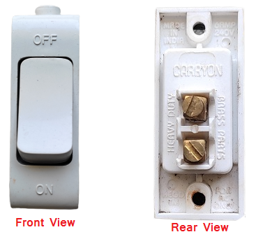
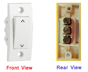
Godown wiring is a technique which we used in large ware houses for lighting purpose, In this technique we use two way switches as well as one way switch Now the question is what is one way switch and one is two way switch ?

So the answer to this question is one way switch has only two terminals while two way switch has three terminals one can easily differentiate between the by only watching their terminals you can also give a look to below pictures of one way and two way switches.

One way Switch
Two way Switch

After watching these pictures you will learn about one way ans two way switches now the question rises how to use this now before these switches in godown wiring we have to learn about the combination of switches used so here is a simple thumb rule that if we have to use 10 number of bulbs in our godown then we have to use total 10 switches for 10 bulbs. out of 10 switches we have to use 9 two way switches and 1 one way switches. Similarly let’s take another example if we have to use 20 bulbs in godown then we have to use 19 two way switches and 1 one way switch, this is the way to use the combination.

Now another question is circuit diagram to be used to connect all these switches and bulbs in godown wiring so here is the answer below

Godown Wiring Circuit Diagram

The above circuit shows the godown wiring of total four bulbs which we are doing with the help of 3 two way switches and 1 one way switch as discussed in above paragraphs, Now one have to follow same circuit for any number of bulbs to be connected and easily do the godown lighting connections.

You can also watch video on godown wiring on the link below:-

Godown Wiring Video

I hope you like this article and learn a lot from this, for such kind of electrical related articles kindly follow my website and also my youtube channel Thanks.

Youtube Channel :- Electrical Stuff 4u

What is Electrical Resistance? Definition and Units.

Resistance is the property of a substance due to which it opposes the flow of electrons (current) through it.

It varies from substance to substance, some substance have low resistance like class A Metals like Silver, Copper and Aluminium. These metals offers very less resistance to flow of electricity through them when we applied potential difference(voltage) across them, so these metals are called good conductors of Electricity.

                                    Those substances which offer relatively greater resistance or hindrance to the flow of electrons through them are called poor conductor or one can say Insulators of electricity like bakelite, Mica, glass, rubber P.V.C. (polyvinyl chloride) and wood etc. These substances are bad conductor of electricity and does allow electric charge to flow through them.

Resistance is donated by symbol R.

Units of Resistance   

SI Unit of Resistance is ohm.

A conductor contain one ohm resistance if it permits one ampere current to flow through it when one volt of potential difference is applied across it.

Bigger units of Resistance are Mega-ohm = 10⁶ ohm , Kilo-ohm = 10³ohm used for insulators having high resistance.

Smaller Units are Milli-ohm = 10ˉ³ohm and Micro-ohm=10ˉ⁶ ohm used for good conductors having low resistance.

Symbol used to donate ohm is Ω.

Also Read:

Electrical Energy

Resistance Laws:-

Resistance R offered by a conductor depends on:

  1. R is directly proportional to length L of conductor.
  2. R is inversely proportional to cross sectional area A of the conductor.
  3. R depends on the nature of material.
  4. R depends on the nature of material.
  5. R also depends on the temperature of conductor.

Neglecting last two factor we get:-

R = ρΙ/A

Where ρ is constant called specific resistance or resistivity.

l is length of conductor.

A is cross sectional area of conductor.

If length l =1metre and area A= 1 metre² then R =ρ

Units of Resistivity

Since R = ρΙ/A

Then from above equation

ρ=AR/l = A metre² * R ohm/ l metre

ρ = ohm-metre

Hence Unit of resistivity is ohm-metre (Ω-m)

Also Visit My Youtube Channel

Electrical Stuff 4u

Basic Electrical MCQ

1. An electric current is the

  1. storage of charge
  2. flow of electrons
  3. ionization of atom
  4. opposition to electrons

Answer: 2

2. The dielectric material used in variable capacitor is generally

  1. air
  2. mica
  3. ceramic
  4. electrolyte

Answer: 1

3. How many electrons will constitute 2 Coulombs of charge?

  1. 6.24 * 1018 electrons
  2. 12.48 * 1018 electrons
  3. 1.602 * 1019 electrons
  4. 3.204 * 1019 electrons

Answer: 2
Explanation: One Coulomb of charge consists of 1/(1.602*10-19) electron that is 6.24 * 1018 electrons. A coulomb is a unit for the charge. Thus, for 2 Coulombs of charge will have 6.24 * 1018 * 2 = 12.48 * 1018 electrons.

4. What is responsible for the current to flow?

  1. Protons
  2. Electrons
  3. Nucleus
  4. Protons and Electrons

Answer: 2
Explanation: For the current to flow in a circuit electrons are required. Electrons are negatively charged and when the potential difference is applied these electrons flow to constitute a current. The current direction is opposite to the electron flow.

5. Which of the following type of circuits in electrical engineering cannot be analyzed using Ohm’s law?

  1. Unilateral
  2. Bilateral
  3. Linear
  4. Conductors

Answer: 1
Explanation: Ohm’s law cannot be used for analyzing unilateral networks as such networks only allow current flow in one direction. A unilateral network can consist diode, transistor, etc.

6. Which of the following is correct about direct current?

  1. Frequency is zero
  2. Can be transported to larger distances with less loss in power
  3. Flows in one direction
  4. Magnitude is constan

Answer: 1
Explanation: A direct current has a fixed value and does not change with time. The frequency of the direct current is equal to zero as it does not change with time.

7. A capacitor consists of two

  1. insulation separated by a dielectric
  2. ceramic plates and one mica disc
  3. silver-coated insulators
  4. conductors separated by an insulator

Answer: 4

8. In a cable capacitor, voltage gradient is maximum at the surface       of the

  1. sheath
  2. earth
  3. conductor
  4. insulator

Answer: 3

9. The capacitance of a cable capacitor depends on

  1. core diameter
  2. ratio of cylinder radii
  3. potential difference
  4. insulation thickness

Answer: 2

10. The time constant of an R-C circuit is defined as the time during     which capacitor charging current becomes ——— percent of its        —— value.

  1. 37, initial
  2. 37, final
  3. 63, initial
  4. 63, final

Answer: 1