Ravi

transformer mcq

Why we need Transformer?

Since Transformer converts electricity from one voltage level to another voltage level as per our requirement, So Transformer is used for electricity transmission purpose.

Hydro Power Plant

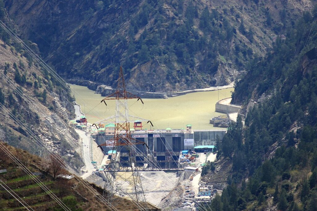
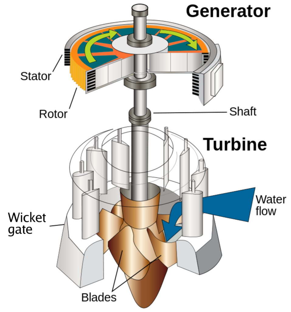
Electricity is generated at Power stations either Hydro Power stations or Thermal Power stations by moving Turbine with water and steam respectively.

Thermal Power Plant
Turbine Generator Mechanism

Both types of Power stations are situated very far away around 1000/1200 KM from residential area because Hydro Power stations are situated at hilly areas where dams constructed over river and water stored in the reservoir for turbine running purpose. Since Dams are constructed in-between mountains which are far away from cities, Also Thermal Power stations are situated near the coal mines where coal is easily available and less transportation of coal required so cost reduces since coal mines are available far from cities

Also Read :

Transformer MCQ

Electric Power

Coal Mines for Thermal Power Plant Steam Generation

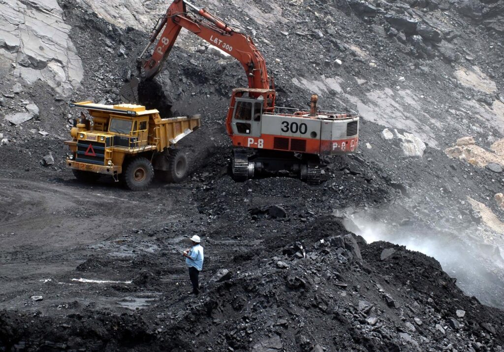
 So Thermal Power stations are also situated far away from cities. Now Electricity is generated in Power stations but we have to use this electricity in houses, shops, Industries which is around 1000/1200 KM away from Power stations, So for that we have to transmit electricity through wires. Since Generating Voltage is 11KV

and if we transmit 11KV from Power stations then due to large current heavy transmission losses takes place and very small amount of electricity reaches at consumers end and maximum part get wasted in form of transmission loss by joules law of heating i.e I²R losses. Now only path to transmit electricity is by lower down the current which is only possible by raising the voltage level, since Voltage is inversely proportional to Current i.e. if Voltage is high then current is low and vice-versa. So we have to raise the voltage levels to higher voltages like 132/220/400/765 KV which is only possible with the help of Transformer.

Transmission Towers

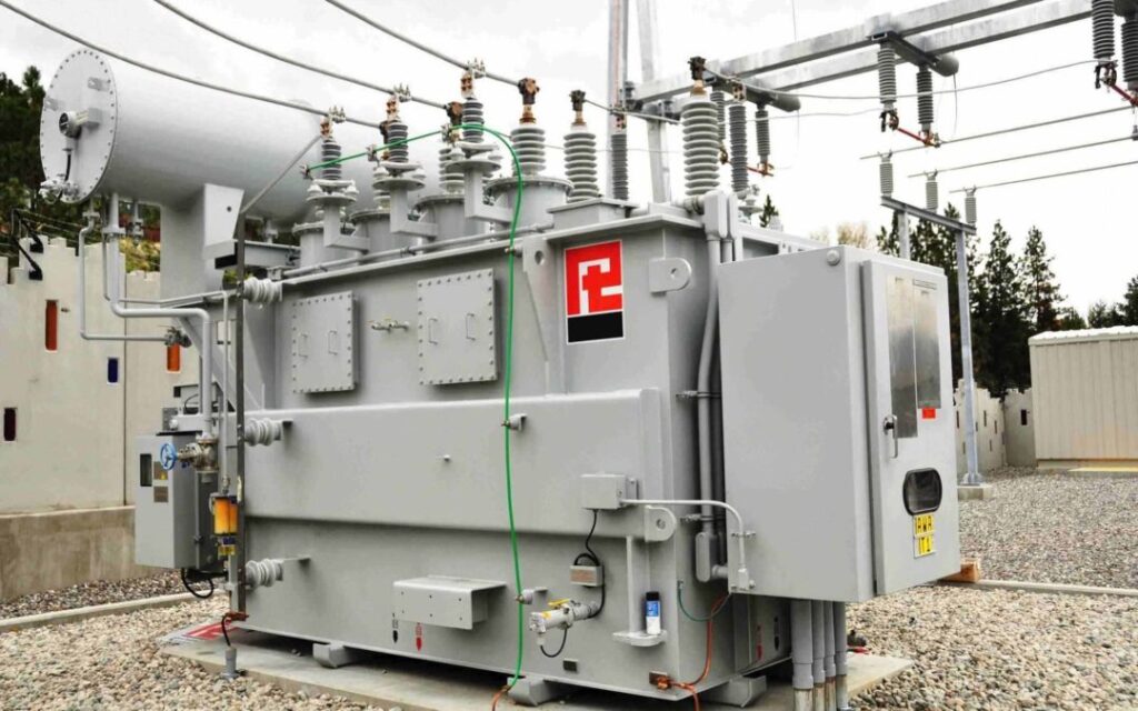
So at Power stations Power Transformer/Step UP Transformer are used which converts low voltage i.e 11 KV into high voltages i.e. 132/220/400/765 KV as per requirement. Then Electricity is transmitted at these voltage levels from Power stations to Sub-stations with the help of large Transmission Towers,which is situated in the vicinity of cities. Due to high voltages transmission losses are almost negligible and maximum electricity reaches at substation. 

Step Down Transformer at Substation

After that at Substation Voltage levels are lower down with the help of again Transformer’s but at sub-stations Step Down Transformers are used where Higher voltages 132/220/400/765 KV gets converted to 33 KV which is also high voltage but used for 30-40 km transmission purpose.

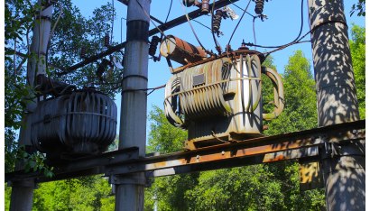
Then this 33 KV Voltage is transmitted to 33 KV Sub-station which is situated in between the city or residential area.Now at 33 KV Sub-station Again Step-Down Transformer is used to convert 33 KV into 11 KV and this voltage is transmitted to Distribution Transformer’s which is installed on H pole structure’s you have already seen near by your houses.

Distribution Transformer

Distribution Transformers are also step down transformers which converts 11 KV into 440 V for three phase and 220 V for single phase which is also called LT supply. Then this voltage is transferred to houses by LT lines and service wires, since Voltage requirement of devices used at our houses is 220 V so LT supply i.e. 220 V is supplied to houses.

So Transformer plays a major role in Electricity transmission and we can’t imagine Electricity transmission without Transformer’s. Also Transformer is very rugged and less maintenance required equipment as there is no moving part in it. It is also called static device.

Also Visit my Youtube Channel for electrical videos

Electrical Stuff 4u

Transformer MCQ

1. When the iron losses of a distribution transformer decreases, then its all day efficiency
  1. increases
  2. decreases
  3. unaffected
  4. none of the above

Answer: 1

2. The main purpose of using core in a transformer is to
  1. decrease iron losses.
  2. decrease reluctance of the common magnetic circuit.  
  3. eliminate magnetic hysteresis
  4. prevent eddy current loss.

Answer: 2

3. A transformer has hysteresis loss of 30 W, at 240 V, 60 Hz. The hysteresis loss at 200 V, 50 Hz will be
  1. 28 W
  2. 25 W
  3. 30 W
  4. 36 W

Answer: 2

4. The functions of using stepped core in transformer is to reduce
  1. eddy current losses
  2. hysteresis losses
  3. volume of copper
  4. reluctance of core

Answer: 3

5. Which part of the transformer is most affected by the overheating?
  1. winding insulation
  2. winding of transformer
  3. transformer core
  4.  transformer tank

Answer: 1

6. When the transformer is loaded then the secondary terminal voltage will fall for
  1. leading power factor.
  2. lagging power factor.
  3. unity power factor.
  4.  lagging and leading power factor.

Answer: 2

7. The full load copper loss and iron loss of transformer are 6400W and 5000W respectively. The copper loss and iron loss at half load will be respectively?
  1. 3200 W and 2500 W
  2. 3200 W and 5200 W
  3. 1600 W and 1250 W
  4. 1600 W and 5000 W

Answer: 4
Explanation : Iron losses do not depend on the load, iron losses remain constant for any load. Therefore iron losses are considered as constant losses. Copper losses vary as square of load current and these are considered as variable losses.

8. In a star-delta transformer, the delta side phase voltage leads the star sides phase voltage by an angle
  1. + 30°.
  2. + 45°.
  3. – 30°.
  4. – 45°.

Answer: 1

9. The chemical used in breather of a transformer should have property of
  1. absorbing moisture.
  2. ionizing air.
  3. absorbing heat.
  4. cleaning oil.

Answer: 1

10. Minimum voltage regulation occurs when the power factor of the load is
  1. lagging
  2. leading
  3. unity
  4. zero

Answer: 2

Transformer MCQ

1. In a transformer zero voltage regulation is achieved at a load power factor which is
  1. leading
  2. lagging
  3. unity
  4. zero

Answer: 1
Explanation : At leading power factor the voltage regulation can be negative or zero. This can be found from this equation % regulation = εxcosθ – εrsinθ

2. What is the magnitude of mutually induced emf, E2 in a transformer?
  1. directly proportional to rate of change of flux and number of secondary turns
  2. inversely proportional to rate of change of flux and number of secondary turns
  3. proportional to rate of change of flux and inversely proportional to number of secondary turns
  4. inversely proportional to rate of change of flux and proportional to number of secondary turns

Answer: 1
Explanation: Due to the supply voltage, a secondary induced emf is produced. V1 is in antiphase with E2 and the magnitude of E2 is proportional to rate of change of flux and number of secondary turns.

3. Which of these will happen in a transformer when the number of secondary turns is less than the number of primary turns?
  1. The voltage gets stepped up
  2. The voltage gets stepped down
  3. The power gets stepped up
  4. The power gets stepped down

Answer: 2
Explanation: According to the fundamentals of electrical engineering, the voltage transformation ratio is the ratio of the number of secondary turns to that of the number of primary turns. When the transformation ratio is less than 1, the step-down operation occurs.

4. Which of the following Transformer can have tap changer?
  1. Power transformer.
  2. Earthing transformer.
  3. Current transformer
  4. Potential transformer

Answer: 1

5. The constant losses in transformer is/are
  1. eddy current loss.
  2. hysteresis loss.
  3. copper loss.
  4. both 1 & 2

Answer: 4
Explanation: Eddy current loss and hysteresis loss are almost independent of load, significantly depending on supply voltage and frequency. As the flux density or flux is constant for a given voltage and frequency, eddy current loss and hysteresis loss remain constant at any load. Therefore, these losses are called constant losses. Copper loss varies as the square of load current and called variable loss.

6. The efficiency of two identical transformers under loaded conditions can be determined by
  1.  open circuit test.
  2. short-circuit test.
  3. back-to-back test.
  4. any of the above.

Answer: 3

7. What is the number of primary turns in a 200/1000 V transformer if the emf per turn is 10V?
  1.  5
  2. 10
  3. 20
  4. 40

Answer: 3
Explanation: According to the electrical engineering fundamentals, the number of primary turns is the ratio of induced emf in the primary to the emf induced per turn. Thus, the number of primary turns in a 200/1000 V transformer with emf per turn of 10V is 200/10 = 20.

8. What is the equivalent resistance of the primary of a transformer with a voltage transformation ratio of 10 and primary resistance of 0.05Ω when referred to secondary?
  1.  0.005
  2. 0.5
  3. 5
  4. 50

Answer: 3
Explanation: According to fundamentals of electrical engineering, the equivalent resistance of the primary of a transformer with a voltage transformation ratio of K and primary resistance of RΩ when referred to secondary is equal to K2*R. Thus, the answer will be 102*0.05 = 5.

9. In a transformer, hysteresis and eddy current losses depend upon
  1.  load current
  2. maximum flux density
  3. supply frequency
  4. both 2 and 3

Answer: 4

10. In a transformer operating at constant voltage if the input frequency increases, the core
  1.  increase
  2. decrease
  3. remains constant
  4. none of the above

Answer: 2

Basic Electrical MCQ

1. An electric current is the

  1. storage of charge
  2. flow of electrons
  3. ionization of atom
  4. opposition to electrons

Answer: 2

2. The dielectric material used in variable capacitor is generally

  1. air
  2. mica
  3. ceramic
  4. electrolyte

Answer: 1

3. How many electrons will constitute 2 Coulombs of charge?

  1. 6.24 * 1018 electrons
  2. 12.48 * 1018 electrons
  3. 1.602 * 1019 electrons
  4. 3.204 * 1019 electrons

Answer: 2
Explanation: One Coulomb of charge consists of 1/(1.602*10-19) electron that is 6.24 * 1018 electrons. A coulomb is a unit for the charge. Thus, for 2 Coulombs of charge will have 6.24 * 1018 * 2 = 12.48 * 1018 electrons.

4. What is responsible for the current to flow?

  1. Protons
  2. Electrons
  3. Nucleus
  4. Protons and Electrons

Answer: 2
Explanation: For the current to flow in a circuit electrons are required. Electrons are negatively charged and when the potential difference is applied these electrons flow to constitute a current. The current direction is opposite to the electron flow.

5. Which of the following type of circuits in electrical engineering cannot be analyzed using Ohm’s law?

  1. Unilateral
  2. Bilateral
  3. Linear
  4. Conductors

Answer: 1
Explanation: Ohm’s law cannot be used for analyzing unilateral networks as such networks only allow current flow in one direction. A unilateral network can consist diode, transistor, etc.

6. Which of the following is correct about direct current?

  1. Frequency is zero
  2. Can be transported to larger distances with less loss in power
  3. Flows in one direction
  4. Magnitude is constan

Answer: 1
Explanation: A direct current has a fixed value and does not change with time. The frequency of the direct current is equal to zero as it does not change with time.

7. A capacitor consists of two

  1. insulation separated by a dielectric
  2. ceramic plates and one mica disc
  3. silver-coated insulators
  4. conductors separated by an insulator

Answer: 4

8. In a cable capacitor, voltage gradient is maximum at the surface       of the

  1. sheath
  2. earth
  3. conductor
  4. insulator

Answer: 3

9. The capacitance of a cable capacitor depends on

  1. core diameter
  2. ratio of cylinder radii
  3. potential difference
  4. insulation thickness

Answer: 2

10. The time constant of an R-C circuit is defined as the time during     which capacitor charging current becomes ——— percent of its        —— value.

  1. 37, initial
  2. 37, final
  3. 63, initial
  4. 63, final

Answer: 1

Basic Electrical MCQ

1. With the rise in temperature the resistance of carbon

  1. decreases
  2. increases
  3. remain constant
  4. none of the above

Answer: 1

2. When number of capacitors are connected in series, then the equivalent capacitance is

  1. increases
  2. decreases
  3. remain same
  4. none of the above

Answer: 2

3. Which of the following elements of electrical engineering cannot be analyzed using Ohm’s law?

  1. Capacitors
  2. Inductors
  3. Transistors
  4. Resistance

Answer: 3
Explanation: Ohm’s law cannot be used for unilateral networks as such networks only allow current flow in one direction. Transistor forms a unilateral network. Thus, Ohm’s law cannot be used on Transistors.

4. According to the fundamentals of electrical engineering, which of these is a correct representation of peak value in an AC Circuit?

  1. RMS value/Peak factor
  2. RMS value*Form factor
  3. RMS value/Form factor
  4. RMS value*Peak factor

Answer: 4
Explanation: A peak factor in an AC circuit represents the ratio of the peak value to the RMS value. The peak factor also called the crest factor indicates how extreme the peaks are present in a waveform.

5. How many cycles will an AC signal make in 2 seconds if its frequency is 100 Hz?

  1. 200
  2. 150
  3. 100
  4. 50

Answer: 1
Explanation: In electrical engineering, the frequency represents the ratio of the number of cycles to the total time. Since frequency is given as 100 Hz and the time is 2 sec thus a total of 200 cycles will be made.

6. Which of the following is correct about the power consumed by R1 and R2 connected in series if the value of R1 is greater than R2?

  1. R1 will consume more power
  2. R2 will consume more power
  3. R1 and R2 will consume the same power
  4. The relationship between the power consumed cannot be established

Answer: 1
Explanation: In the introduction to electrical engineering it is explained that the power can be expressed as P = I2*R. When two resistors are connected in series the current flowing through the resistors is the same and thus, power consumed by the larger resistor will be more.

7. What kind of quantity is an Electric potential?

  1. Dimensionless quantity
  2. Tensor quantity
  3. Vector quantity
  4. Scalar quantity

Answer: 4
Explanation: Electric potential refers to the work done to bring a unit positive charge from a point with higher potential to a point with lower potential. Since electric potential only has magnitude but no direction, it is a scalar quantity.

8. Who defined electric current and devised a method to measure current?

  1. Andre-Marie Ampere
  2. Nikola Tesla
  3. Alessandro Antonio Volta
  4. Michael Faraday

Answer: 1
Explanation: Andre-Marie Ampere is a French physicist and mathematician who defined electric current and devised a method to measure current in the 1820s.

9. An inductor is a device which store energy in the form of

  1. magnetic field
  2. electric field.
  3. both electric and magnetic field.
  4. voltage and current.

Answer: 1

10. A capacitor is a device designed to store energy in the

  1. magnetic field
  2. electric field.
  3. both electric and magnetic field.
  4. plates

Answer: 2

Transformer Overview

What is Transformer?

Transformer is an AC machine that transfers electrical energy from one electrical circuit to another. Since there is no moving part in Transformer, it is also called Static device. Due to its static nature it requires minimum amount of repair and maintenance.


Types of Transformer

(1) Step-up Transformer:- When Output Voltage of a  Transformer is higher than its input Voltage, it is called step up transformer. Such transformer’s are used at Power stations where generating voltage i.e. 11 KV is raised to higher levels i.e. 66/132/220/400 KV for transmission purpose to Sub-stations.

(2) Step Down Transformer:- When Output Voltage of a Transformer is lower than its input Voltage, it is called step down transformer. Such Transformer’s are used at Sub-stations to lower down voltage from 66/132/220/400 KV to 33KV and 11 KV for distribution to various Industrial Consumer’s and also Distribution Transformer’s to fed house hold consumers. 

(3) Distribution Transformer:- These type of Transformer is used to convert 11KV voltage level to 440V which is used by House-hold various commercial consumers like shops, Panchayat ghar’s etc. Distribution Transformers are mostly seen at vicinity of house-hold consumers installed over H type structure. Since it converts HT voltage to LT voltage so these are used at nearby consumer’s to eliminate voltage drops